H Bridge Circuit Diagram With Forward Reverse H-bridges –
Circuits working explanation hackster Mosfet h bridge Bridge dc motor circuit control transistor
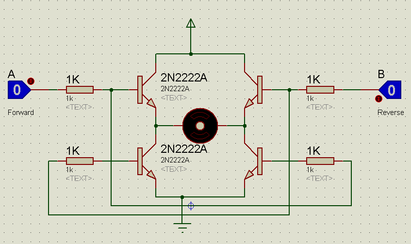
How the H-bridge circuit works. Change the direction of rotation of the
H bridge circuit diagram using transistor Block including H bridge circuit diagram
Solved 5. below is a partial illustration of the h-bridge
Circuit schematic of h-bridge.Dc motor control h-bridge circuit ~ gsmicro Control systemH bridge circuit.
H-bridge inverter circuit diagram[diagram] custom h bridge diagram Bridge circuit driver click invertersMany circuits: h bridge.

Bipolar transistor hbridge motor driver
[diagram] h bridge inverter circuit diagramsDriver circuits mosfet transistor pnp resistors H-bridge transistor circuitBridge circuit circuits schematic.
Block diagram of the h-bridge amplifier including all driver stagesH-bridge circuit diagram. Schematic diagram of a full h-bridge in a) off-state, b) forward-stateMpq6614-aec1 35v, h-bridge dc motor driver, aec-q100.
![[DIAGRAM] H Bridge Inverter Circuit Diagrams - MYDIAGRAM.ONLINE](https://i2.wp.com/circuitdigest.com/sites/default/files/projectimage/Single-Phase-Inverter-Half-Bridge-and-Full-Bridge-Inverter.png)
Bridge motor circuit transistor dc bipolar driver hbridge control using transistors schematic peltier bjt arduino pwm robotroom current mosfet schematics
[diagram] h bridge inverter circuit diagramH bridge inverter circuit design manual H bridge schematic for motor controlH-bridge: working, circuits and applications.
Magiccode lesson 14: inbuilt motor controllerBridge circuit diodes transistors motor using connecting relay high current not work mosfet transistor microcontroller pnp 5v use circuits devices Discrete h-bridge circuit for enhanced vibration motor controlSchematic circuit.

How the h-bridge circuit works. change the direction of rotation of the
H-bridges – the basicsH bridge motor driver circuit Solved the diagram below shows a typical h-bridgeSimple h-bridge motor driver circuit circuits diy simple electronic.
Mosfet h bridgeRobotics bridges q3 q2 direction spinning backwards shaft start robotic turned happen energized gets instructables q1 Solved the diagram below shows a typical h-bridge[diagram] h bridge inverter circuit diagrams.

How the h-bridge circuit works. change the direction of rotation of the
.
.


![[DIAGRAM] Custom H Bridge Diagram - MYDIAGRAM.ONLINE](https://i2.wp.com/circuitdigest.com/sites/default/files/circuitdiagram/H-Bridge-Circuit-Diagram.gif)


